
Products
Ferrofluid for Corrosive Gas & Dust Blocking
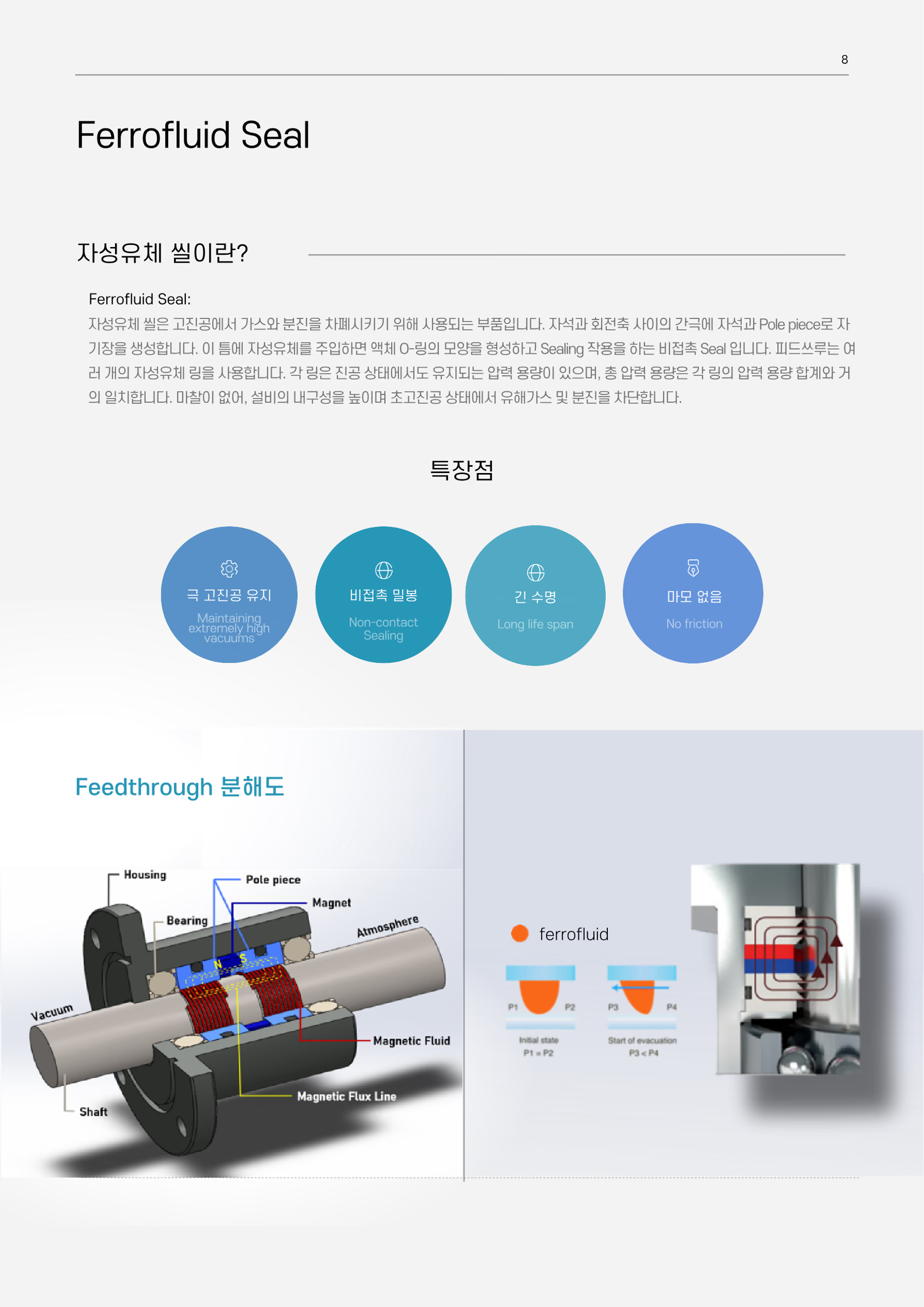
Around rotating shafts, our ferrofluid-based non-contact sealing structure blocks corrosive-gas leakage, external dust ingress, and vacuum-level degradation. Held within a magnetic field, the ferrofluid permits rotary motion while stably preventing the migration of gases, dust, and contaminants.
Non-contact sealing
Ferrofluid held in a magnetic field forms a liquid O-ring sealing film.
Gas & dust blocking
Stably blocks the migration of active/inactive gases and dust.
High vacuum retention
Short pump-down time with a consistently maintained vacuum level.
Long life · wear-free
No mechanical friction means fewer particles and a long service life.
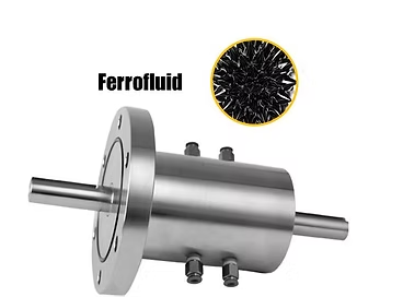
What problem does a ferrofluid seal solve?
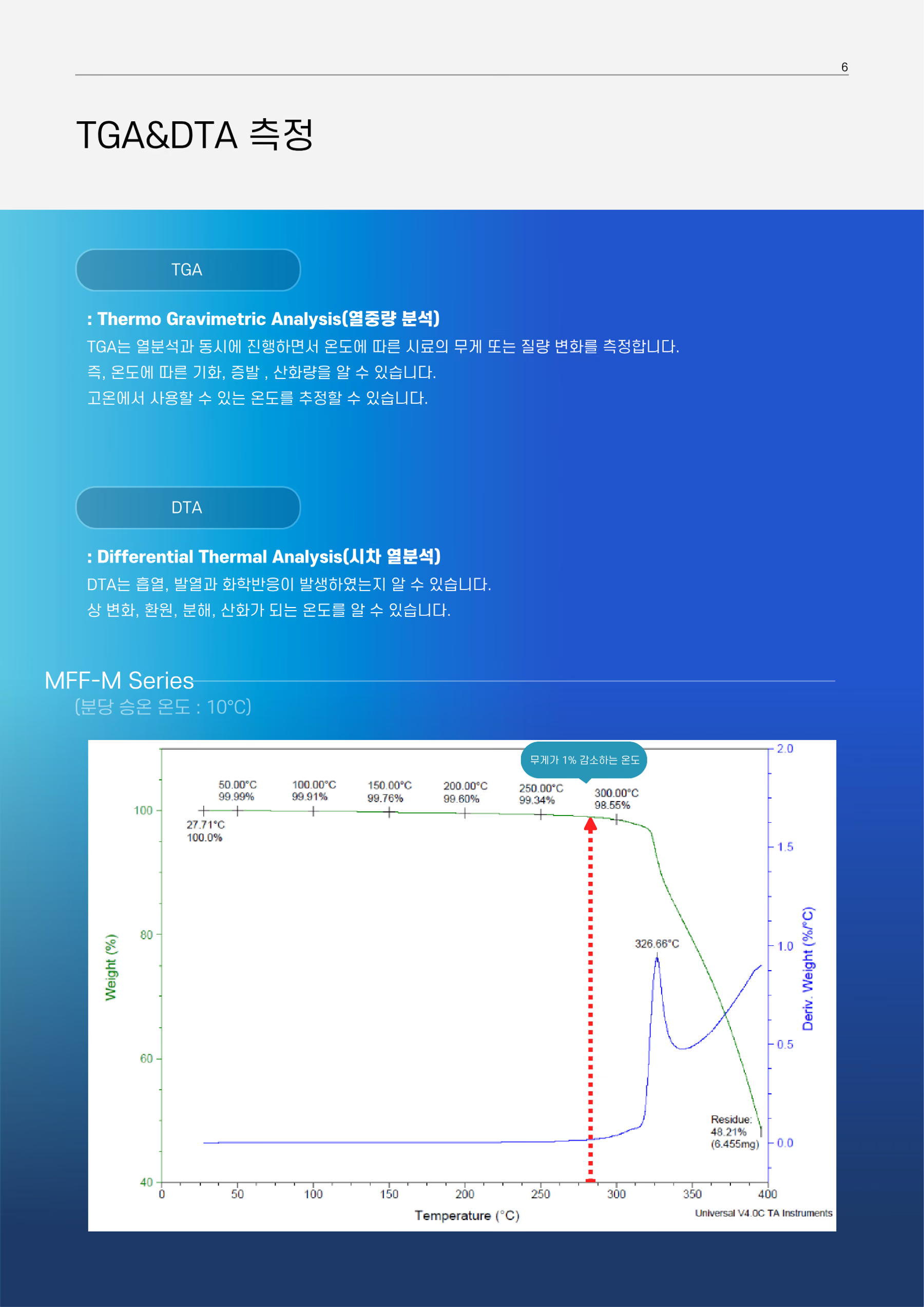
A ferrofluid seal forms a liquid O-ring held in place by a magnetic field around a rotating shaft, blocking corrosive-gas leakage, dust ingress, and vacuum loss while the shaft keeps turning. The MFF/MFF-M series (PFPE) for corrosive gases holds a vapor pressure of 1.5×10⁻¹⁰ Pa or lower at 20℃ and a 1 wt% weight-loss temperature above 280℃; the MFS (silicone) and MFH (hydrocarbon) series cover non-corrosive gases.
- Which product is used in corrosive-gas environments?
- The MFF/MFF-M series. A Perfluoro-Polyether (PFPE) carrier fluid gives it chemical stability and low vapor pressure, suppressing rotary-shaft leakage and corrosion on the active-gas lines of semiconductor and display processes.
- How does it differ from a mechanical seal?
- A ferrofluid seal has no contact friction, so it generates fewer particles, wears less, and lasts longer. Leak test data also shows a short pump-down time and a consistently maintained vacuum level.
- How were heat resistance and vapor pressure verified?
- Heat resistance was measured at KITECH (Korea Institute of Industrial Technology) by TGA and DTA at a 10℃/min ramp, and vapor pressure was measured at KOPTRI (Korea Polymer Testing & Research Institute) using the OECD TG 104 effusion method. The measurement data and test results are available as PDFs on the Technical Information page.
- How does it compare with competing products?
- For active-gas PFPE, our MFF-M series reaches 1 wt% weight loss above 280℃. Under the same TGA conditions, S-company (Japan, F-310), M-company (Japan, MFF-03) and L-company (UK, F-9) fall between 158℃ and 185℃ — a gap of roughly 100℃. Note that the competing figures are measured on base oil while ours are measured on the finished ferrofluid, so the conditions are not identical.
Ferrofluid for Corrosive Gas
Active (corrosive) gas blocking
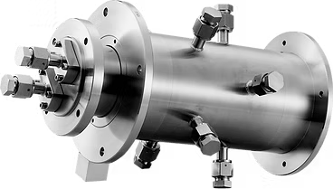
In corrosive-gas environments, a Perfluoro-Polyether (PFPE) carrier fluid ensures chemical stability and low vapor pressure. It suppresses rotary-shaft leakage and corrosion on the active-gas lines of semiconductor and display processes.
- Ferrofluid For Corrosive GasFor active (corrosive) gas environments
- Carrier fluidPerfluoro-Polyether (PFPE)
Specification (MFF / MFF-M Series)
| Model | Saturation Magnetization | Viscosity | Vapor Pressure | Helium gas leak (Torr·L/s) | 1 wt% loss Temp. (TGA) | Pour point | Density | |
|---|---|---|---|---|---|---|---|---|
| Gauss | mPa·s (cP) at 27℃ | Pa at 20℃ | Torr (mmHg) at 20℃ | Less than 1E-11 | ℃ | ℃ | g/cm³ | |
| MFF-M4251 | 420 | 5,100 | <1.5E-10 | <1.2E-12 | Ok | >280 | <-40 | 2.198 |
| MFF-M5070 | 500 | 7,000 | <1.5E-10 | <1.2E-12 | Ok | >280 | <-40 | 2.240 |
| MFF-R6085 | 600 | 8,500 | <1.5E-10 | <1.2E-12 | Ok | >140 | <-40 | 2.25 |
| MFF-R5050 | 500 | 5,000 | <1.5E-10 | <1.2E-12 | Ok | >140 | <-40 | 2.2 |
| MFF-R4020 | 400 | 2,000 | <1.5E-10 | <1.2E-12 | Ok | >140 | <-40 | 2.14 |
- Measurement conditions follow the unit notation in each column (viscosity at 27℃, vapor pressure at 20℃).
- Vapor pressure was measured at KOPTRI (Korea Polymer Testing & Research Institute) using the OECD TG 104 effusion method; the data is available on the Technical Information page.
Leak Test Data
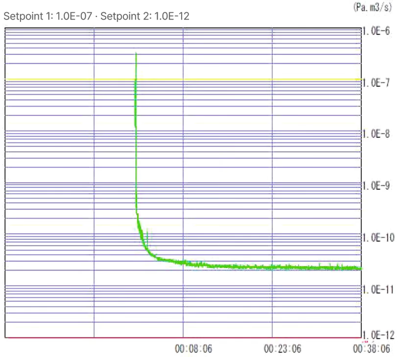
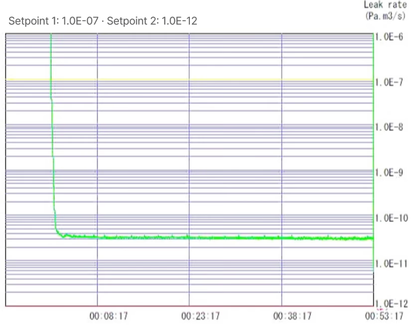
The pump-down time is short, and the vacuum level is maintained consistently.
| Model | Test date | Setpoint 1 | Setpoint 2 | Time to settle | Settled leak rate |
|---|---|---|---|---|---|
| Pa·m³/s | Pa·m³/s | min (approx.) | Pa·m³/s | ||
| MFF-M4251 | 2024-07-03 | 1.0E-07 | 1.0E-12 | 38 | 1E-10 ~ 1E-11 |
| MFF-M5070 | 2024-09-11 | 1.0E-07 | 1.0E-12 | 53 | 1E-10 ~ 1E-11 |
- The rate settles without leak hunting, and the vacuum level stays constant afterwards.
- The charts below are the original instrument records behind this table.
Ferrofluid for Non-Corrosive Gas
Inactive (non-corrosive) gas blocking
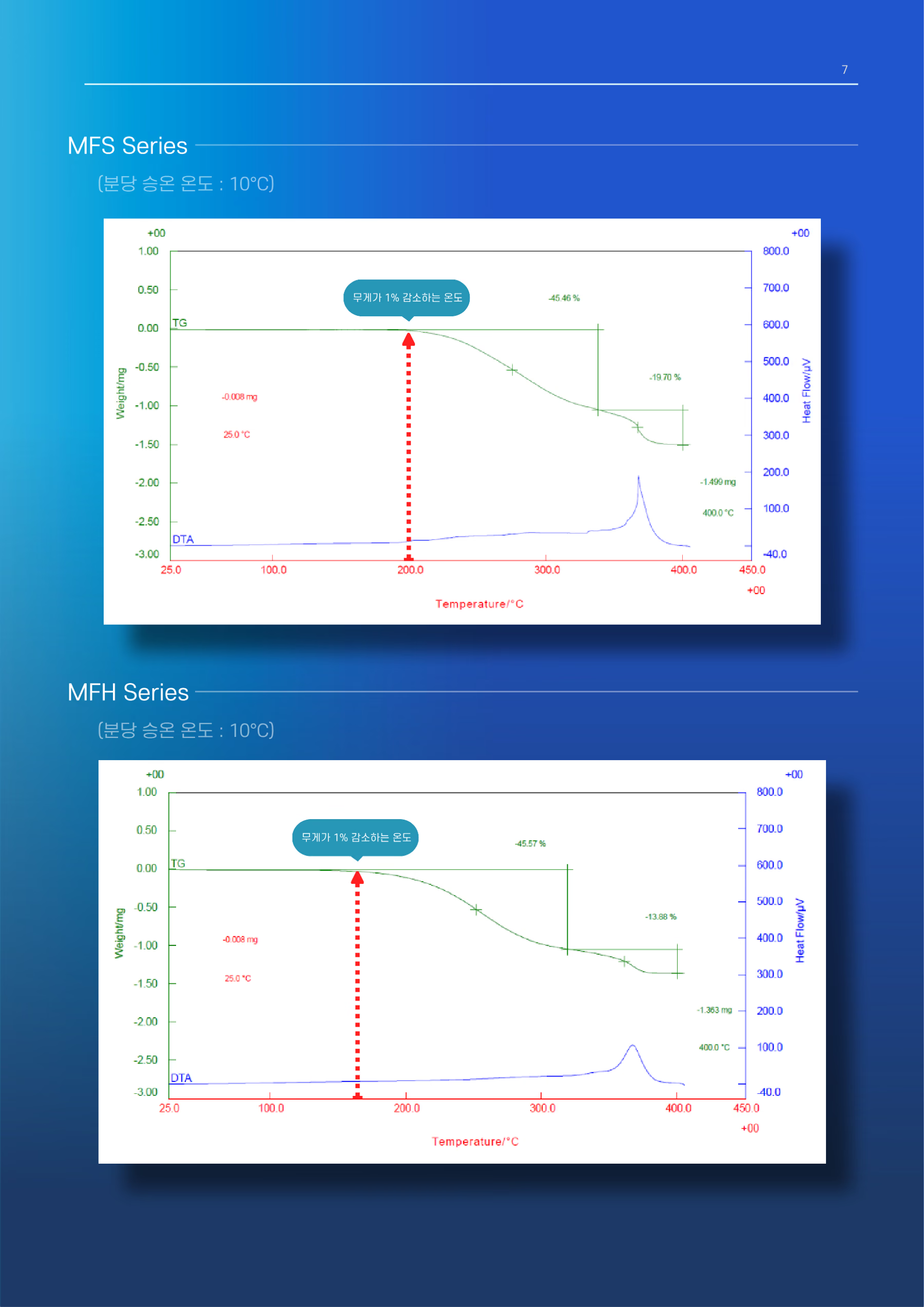
In non-corrosive-gas environments, viscosity, saturation magnetization, temperature characteristics, and the carrier fluid can be selected to match operating conditions. The MFS series is silicon-based and the MFH series hydrocarbon-based.
- Ferrofluid For Non-Corrosive GasFor inactive (non-corrosive) gas environments
- Carrier fluidMFS series – Silicon / MFH series – Hydrocarbon
Specification (MFS / MFH Series)
| Model | Saturation Magnetization | Viscosity | Vapor Pressure | Helium gas leak (Torr·L/s) | 1 wt% loss Temp. (TGA) | Pour point | Density | |
|---|---|---|---|---|---|---|---|---|
| Gauss | mPa·s (cP) at 27℃ | Pa at 20℃ | Torr (mmHg) at 20℃ | Less than 1E-11 | ℃ | ℃ | g/cm³ | |
| MFS-7390 | 730 | 9,000 | <5E-11 | <3.75E-13 | Ok | 200 | <-40 | 1.50 |
| MFS-6022 (MFS-630) | 600 | 2,200 | <5E-11 | <3.75E-13 | Ok | 200 | <-40 | 1.39 |
| MFS-5009 (MFS-513) | 500 | 900 | <5E-11 | <3.75E-13 | Ok | 200 | <-40 | 1.31 |
| MFS-4005 (MFS-407) | 400 | 500 | <5E-11 | <3.75E-13 | Ok | 200 | <-40 | 1.21 |
| MFH-7730 | 770 | 3,000 | <5E-11 | <3.75E-13 | Ok | 170 | <-40 | 1.52 |
| MFH-6206 | 620 | 650 | <5E-11 | <3.75E-13 | Ok | 170 | <-40 | 1.39 |
| MFH-5002 (MFH-503) | 500 | 210 | <5E-11 | <3.75E-13 | Ok | 170 | <-40 | 1.30 |
| MFH-4401 | 440 | 150 | <5E-11 | <3.75E-13 | Ok | 170 | <-40 | 1.22 |
- Measurement conditions follow the unit notation in each column (viscosity at 27℃, vapor pressure at 20℃).
- Vapor pressure was measured at KOPTRI (Korea Polymer Testing & Research Institute) using the OECD TG 104 effusion method; the data is available on the Technical Information page.
TGA & DTA Measurement
Thermal Stability
TGA (Thermo Gravimetric Analysis) and DTA (Differential Thermal Analysis) analyze weight loss and thermal behavior with temperature to evaluate the stability and usable temperature range of the carrier fluid.
Ferrofluid Seal
What is a ferrofluid seal?
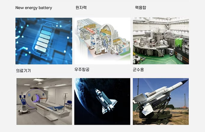
Equipment & Fields Using Ferrofluid

Company Information

| Address | #403, Bldg 3, Gyeonggi Technopark, 705 Haean-ro, Sangnok-gu, Ansan-si, Gyeonggi-do, Korea (15588) |
|---|---|
| Contact | TEL) 031-500-4633 FAX) 031-500-4631 |
| magron@magron.co.kr | |
| Website | (KO) www.ferrofluidmagron.co.kr (EN) www.ferrofluidmagron.com |