
Products
Feedthrough
High-Reliability Vacuum Feedthrough Solutions Based on Magnetic Fluid Seal
A feedthrough is a core component that transmits rotary motion, linear motion, gas, electrical signals, and more into a vacuum chamber or sealed equipment while maintaining the internal vacuum level and cleanliness.
A Magnetic Fluid Seal-based feedthrough blocks gas leakage, external contaminant ingress, and dust ingress through a ferrofluid sealing structure formed around the rotating shaft. It suits equipment requiring high reliability and long life, such as semiconductors, displays, vacuum deposition, ion implantation, robotic transfer, aerospace, and research equipment.
Vacuum Sealing
Stably maintains the pressure and cleanliness inside the vacuum chamber.
Rotary Motion Transfer
Transfers external power into the equipment through the rotating shaft.
Low Particle Generation
Reduces particle generation with a ferrofluid sealing structure.
Custom Specification
Specifications can be reviewed to match shaft diameter, rotation speed, and vacuum conditions.
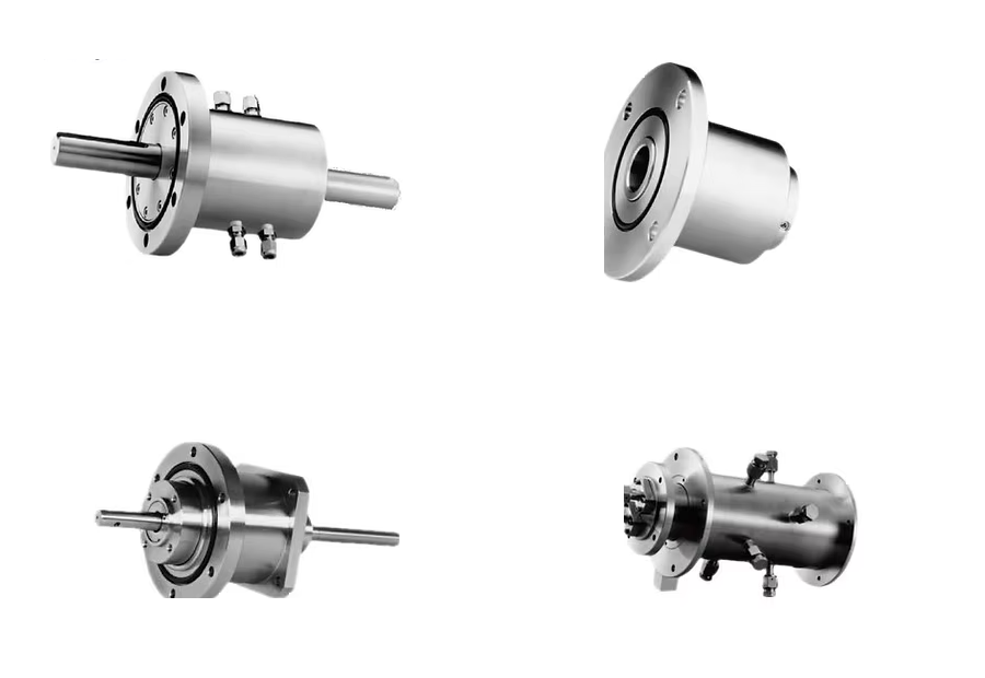
What is a vacuum feedthrough?
A feedthrough transmits rotary or linear motion, gas, or electrical signals from outside a vacuum chamber to the inside while preserving the chamber’s vacuum level and cleanliness. MAGRON feedthroughs seal the rotating shaft without contact using ferrofluid, reducing both leakage and particle generation.
- What types are available?
- Miniature rotary, through-hole mount, flange mount, heavy-duty, and hollow-shaft cartridge, flange, and cantilever types. A combined-drive version pairing a three-axis coaxial spindle with a 50 mm linear stroke is applied to Cluster Tools, 300 mm wafers, LCD large-substrate processing, and in-vacuum transfer robots.
- Can it be made to order?
- Yes. Share the shaft diameter, rotational speed, required vacuum level, flange specification, and gas type, and we will review a specification that matches those conditions.
- Is leak performance data available?
- Helium leakage is below 10⁻¹² Pa·m³/s (10⁻¹¹ Torr·ℓ/s), the attainable vacuum is on the order of 10⁻⁶ Pa (10⁻⁸ Torr), and the operating temperature range is 0–150℃. Torque capacity and bearing, housing and shaft materials are listed per model in the specification tables on this page.
Standard Rotary Feedthroughs
Standard Rotary Feedthroughs
Standard rotary feedthroughs selected by shaft diameter and mounting method. They support a wide range of shaft diameters from miniature to heavy-duty.
Miniature Feedthrough
Miniature Rotary Feedthrough
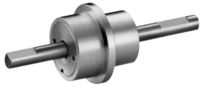
For compact equipment that must transmit rotary motion in limited space while maintaining vacuum sealing. Applied to research equipment, small vacuum chambers, and precision drive modules.
Standard Type (MML)
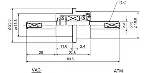
| Shaft Diameter | 004 | 005 | 006 |
|---|---|---|---|
| A | Ø4 | Ø5 | Ø6 |
| E | 0.5Dp. / 10Lg. | 0.5Dp. / 10Lg. | 0.5Dp. / 10Lg. |
| Model Number | MML004NN | MML005NN | MML006NN |
|---|---|---|---|
| Torque capacity (kg·cm) | 5.8 | 6.4 | 6.4 |
| Vacuum pressure Pa,(Torr) | 10⁻⁶, (10⁻⁸) | ||
| Leakage rate [He] (Pa·m³/sec) | <10⁻¹² | ||
| (Torr·ℓ/sec) | <10⁻¹¹ | ||
| Pressure capacity [Static] (kg/cm²) | 2 | ||
| Temperature range (°C) | 0 – 150 | ||
| Gas compatibility | Inert Gas | ||
| Bearing type | 686 | 686 | 686 |
| Bearing material | SUS440C | ||
| Housing material | SUS303 | ||
| Shaft material | SUS630 | ||
Threaded Type (MSL)
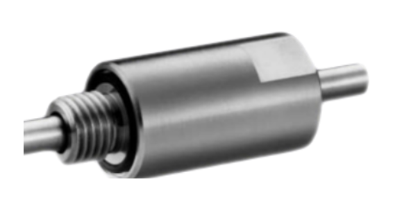
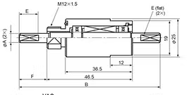
| Shaft Diameter | 004 | 005 | 006 |
|---|---|---|---|
| A | Ø4 | Ø5 | Ø6 |
| B | 76.5 | 76.5 | 76.5 |
| E | 0.5Dp. / 10Lg. | 0.5Dp. / 10Lg. | 0.5Dp. / 10Lg. |
| F | 15 | 15 | 15 |
| Model Number | MSL004NN | MSL005NN | MSL006NN |
|---|---|---|---|
| Torque capacity (kg·cm) | 5.8 | 6.4 | 6.4 |
| Vacuum pressure Pa,(Torr) | 10⁻⁶, (10⁻⁸) | ||
| Leakage rate [He] (Pa·m³/sec) | <10⁻¹² | ||
| (Torr·ℓ/sec) | <10⁻¹¹ | ||
| Pressure capacity [Static] (kg/cm²) | 2 | ||
| Temperature range (°C) | 0 – 150 | ||
| Gas compatibility | Inert Gas | ||
| Bearing type | 686 | 686 | 686 |
| Bearing material | SUS440C | ||
| Housing material | SUS303 | ||
| Shaft material | SUS630 | ||
- Reactive-gas compatible feedthroughs are also available. (Specify application when requesting a quotation or placing an order.)
Through Hole Mount Feedthroughs
Through-Hole Mount Feedthrough
Installed by passing through an equipment wall or plate. It connects the vacuum chamber to the external drive while blocking vacuum leakage around the rotating shaft.
Ø6 – Ø10
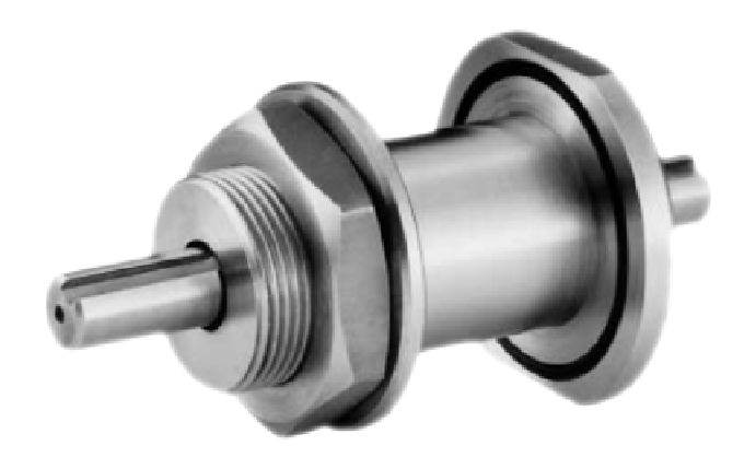
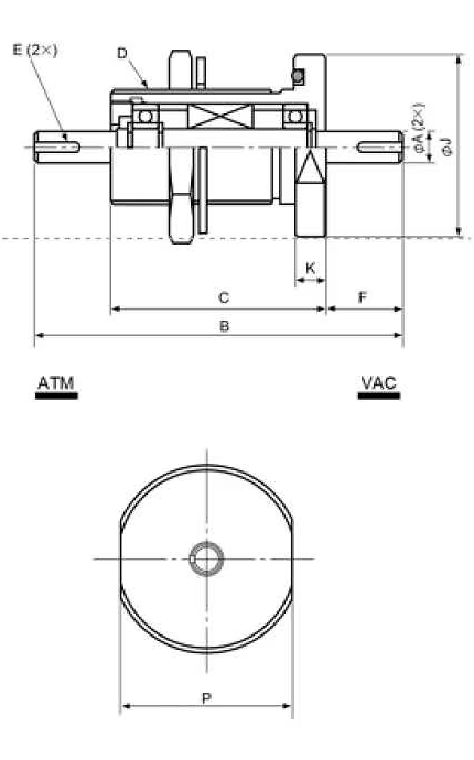
| Shaft Diameter | 006 | 010 |
|---|---|---|
| A | Ø6 | Ø10 |
| B | 97.5 | 97.5 |
| C | 57.5 | 57.5 |
| D | M32 × 1.5 | M38 × 1.5 |
| E | 0.5Dp. × 12Lg. (flat) | 3W × 1.8Dp. × 14Lg. (keyway) |
| F | 20 | 25 |
| J | 55 | 60 |
| K | 10 | 10 |
| P | 49 | 55 |
| Model Number | MML006NN | MNF006NN | MML010NN | MNF010NN |
|---|---|---|---|---|
| Torque capacity (kg·cm) | 9.7 | 9.7 | 62 | 62 |
| Vacuum pressure Pa,(Torr) | 10⁻⁶, (10⁻⁸) | 10⁻⁵, (10⁻⁷) | 10⁻⁶, (10⁻⁸) | 10⁻⁵, (10⁻⁷) |
| Leakage rate [He] (Pa·m³/sec) | <10⁻¹² | |||
| (Torr·ℓ/sec) | <10⁻¹¹ | |||
| Pressure capacity [Static] (kg/cm²) | 2.5 | 2 | 2.5 | 2 |
| Temperature range (°C) | 0 – 150 | |||
| Gas compatibility | Inert | Active | Inert | Active |
| Bearing type | 627 | 627 | 6001 | 6001 |
| Bearing material | SUS440C | |||
| Housing material | SUS303 | SUS304 | SUS303 | SUS304 |
| Shaft material | SUS630 | |||
Ø12 – Ø20 (water cooling)
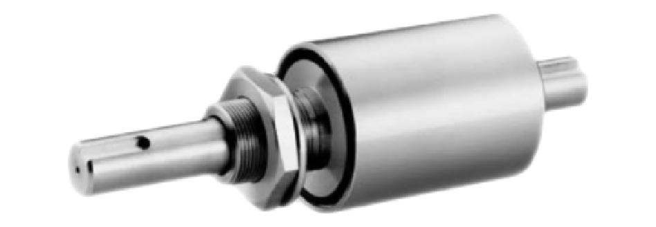
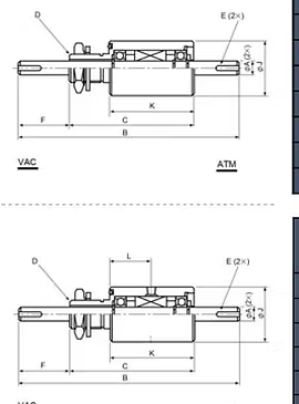
| Shaft Diameter | 012 | 020 |
|---|---|---|
| A | Ø12 | Ø20 |
| B | 179 | 211 |
| C | 109 | 121 |
| D | M25 × 1.5 | M30 × 1.5 |
| E (keyway) | 4W × 2.5Dp. × 20Lg. | 6W × 3.5Dp. × 25Lg. |
| F | 40 | 55 |
| J | 48 | 63 |
| K | 74 | 82 |
| L | 36.5 | 40.5 |
| Model Number | MTL012NN | MTF012NN | MTL020NN | MTF020NN |
|---|---|---|---|---|
| Torque capacity (kg·cm) | 124 | 124 | 615 | 615 |
| Vacuum pressure Pa,(Torr) | 10⁻⁶, (10⁻⁸) | 10⁻⁵, (10⁻⁷) | 10⁻⁶, (10⁻⁸) | 10⁻⁵, (10⁻⁷) |
| Leakage rate [He] (Pa·m³/sec) | <10⁻¹² | |||
| (Torr·ℓ/sec) | <10⁻¹¹ | |||
| Pressure capacity [Static] (kg/cm²) | 2.5 | 2 | 2.5 | 2 |
| Temperature range (°C) | 0 – 150 | |||
| Gas compatibility | Inert | Active | Inert | Active |
| Bearing type | 6002 | 6002 | 6005 | 6005 |
| Bearing material | SUS440C | |||
| Housing material | SUS303 | SUS304 | SUS303 | SUS304 |
| Shaft material | SUS630 | |||
- Tapped bore type model number should change to MF0-000-WN.
Flange Mount Feedthroughs
Flange Mount Feedthrough
A type fixed to equipment by flange fastening. With high installation stability and easy maintenance, it is widely applied to industrial vacuum and process equipment.
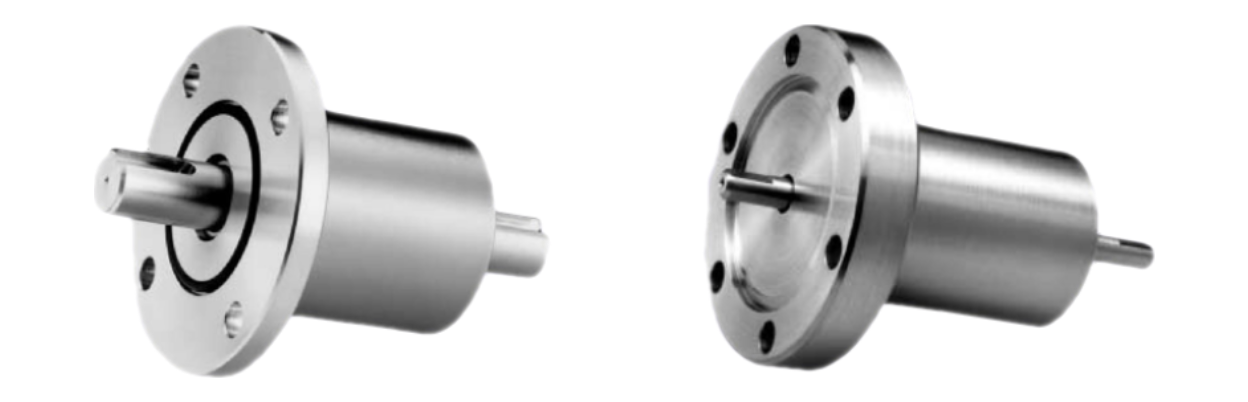
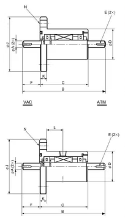
| Shaft Diameter | 006 | 010 | 012 | 020 |
|---|---|---|---|---|
| A | Ø6 | Ø10 | Ø12 | Ø20 |
| B | 97.5 | 119.5 | 133.5 | 151.5 |
| C | 57.5 | 69.5 | 73.5 | 81.5 |
| D | 38 | 44 | 48 | 63 |
| E | 0.5Dp. × 12Lg. | 3W × 1.8Dp. × 14Lg. | 4W × 2.5Dp. × 20Lg. | 6W × 3.5Dp. × 25Lg. |
| F | 20 | 25 | 30 | 35 |
| J | 80 | 80 | 90 | 105 |
| K | 10 | 10 | 10 | 10 |
| L | 18 | 24 | 27 | 31 |
| N | PD60/4-□10 | PD60/4-□10 | PD70/4-□10 | PD85/4-□10 |
| Model Number | MFL006NN | MFL010NN | MFL012NN | MFL020NN | MFF006NN | MFF010NN | MFF012NN | MFF020NN |
|---|---|---|---|---|---|---|---|---|
| Torque capacity (kg·cm) | 9.7 | 62 | 124 | 615 | 9.7 | 62 | 124 | 615 |
| Vacuum pressure Pa,(Torr) | 10⁻⁶, (10⁻⁸) | 10⁻⁶, (10⁻⁸) | 10⁻⁶, (10⁻⁸) | 10⁻⁶, (10⁻⁸) | 10⁻⁵, (10⁻⁷) | 10⁻⁵, (10⁻⁷) | 10⁻⁵, (10⁻⁷) | 10⁻⁵, (10⁻⁷) |
| Leakage rate [He] (Pa·m³/sec) | <10⁻¹² | |||||||
| (Torr·ℓ/sec) | <10⁻¹¹ | |||||||
| Pressure capacity [Static] (kg/cm²) | 2 | 2 | 2 | 2 | 2.5 | 2.5 | 2.5 | 2.5 |
| Temperature range (°C) | 0 – 150 | |||||||
| Gas compatibility | Inert | Inert | Inert | Inert | Active | Active | Active | Active |
| Bearing type | 627 | 6001 | 6002 | 6005 | 627 | 6001 | 6002 | 6005 |
| Bearing material | SUS440C | |||||||
| Housing material | SUS303 | SUS303 | SUS303 | SUS303 | SUS304 | SUS304 | SUS304 | SUS304 |
| Shaft material | SUS630 | |||||||
- Conflat flange or any other defined configuration may be specified and is available as an option.
- Tapped bore for tube fitting is available for high-temperature or high-rotation-speed applications (model number changes to MF0-000-WN).
- Shaft length and terminations may be specified by the user.
Heavy Duty Feedthroughs
Heavy-Duty Feedthrough
For heavy-process equipment requiring large shaft diameters and high torque. Dedicated bearings for VAC/ATM each maintain stable sealing even under high load and high-speed rotation.
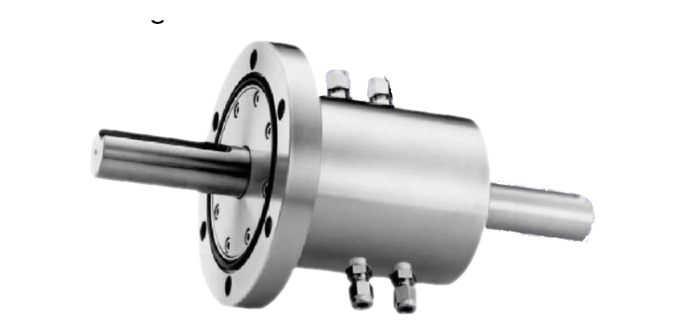
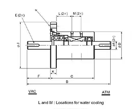
| Shaft Diameter | 020 | 025 | 030 | 040 | 050 |
|---|---|---|---|---|---|
| A | Ø20 | Ø25 | Ø30 | Ø40 | Ø50 |
| B | 255 | 288 | 321 | 357 | 406 |
| C | 135 | 138 | 141 | 157 | 166 |
| D | 85 | 95 | 105 | 125 | 140 |
| E (keyway) | 6W × 3.5Dp. × 50Lg. | 7W × 4Dp. × 63Lg. | 10W × 5Dp. × 80Lg. | 12W × 5Dp. × 90Lg. | 14W × 5.5Dp. × 110Lg. |
| F | 60 | 75 | 90 | 100 | 120 |
| J | 145 | 160 | 160 | 185 | 210 |
| K | 18 | 18 | 20 | 22 | 24 |
| L | 48 | 50 | 50 | 55.5 | 59.5 |
| M | 29 | 29 | 29 | 33 | 33 |
| N | PD120/6-□12 | PD135/6-□12 | PD135/6-□12 | PD160/8-□12 | PD185/8-□12 |
| Model Number | MFL020WH | MFL025WH | MFL030WH | MFL040WH | MFL050WH |
|---|---|---|---|---|---|
| Torque capacity (kg·cm) | 616 | 1066 | 1706 | 3413 | 6106 |
| Vacuum pressure Pa,(Torr) | 10⁻⁵, (10⁻⁷) | ||||
| Leakage rate [He] (Pa·m³/sec) | <10⁻¹² | ||||
| (Torr·ℓ/sec) | <10⁻¹¹ | ||||
| Pressure capacity [Static] (kg/cm²) | 3 | ||||
| Temperature range (°C) | 0 – 150 | ||||
| Bearing type (VAC) | 7206CDF | 7207CDF | 7208CDF | 7210CDF | 7212CDF |
| Bearing type (ATM) | 6205 | 6206 | 6207 | 6009 | 6211 |
| Bearing material | SUJ2 | ||||
| Housing material | SUS303 | ||||
| Shaft material | SUS630 | ||||
- A coaxial shaft cooling system is available for high-temperature or high-rotational-speed applications.
Hollow Shaft Feedthroughs
Hollow Shaft Feedthroughs
Hollow-shaft feedthroughs whose central through-structure lets wiring, gas lines, and shafts pass together. Three types are offered by mounting method.
Hollow Shaft — Cartridge Type
Hollow Shaft · Cartridge Type
A hollow-shaft feedthrough whose central through-structure lets wiring, shafts, and gas lines pass together. It is inserted into the equipment housing in cartridge form.
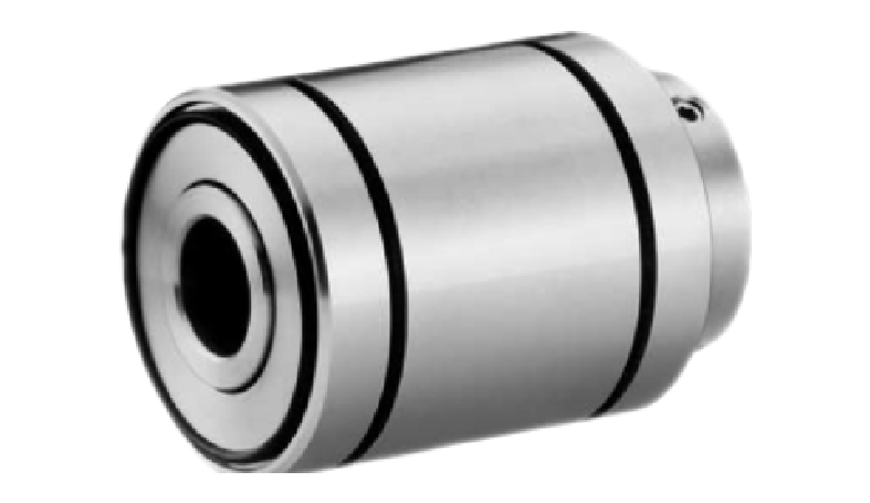
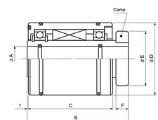
| Shaft Diameter | 010 | 020 | 025 | 030 | 040 | 050 | 075 |
|---|---|---|---|---|---|---|---|
| A | Ø10 | Ø20 | Ø25 | Ø30 | Ø40 | Ø50 | Ø75 |
| B | 78 | 82.5 | 88 | 93 | 96 | 98 | 115 |
| C | 64 | 68.5 | 74 | 79 | 80 | 82 | 96 |
| D | 48 | 58 | 63 | 73 | 88 | 98 | 137 |
| E | 34 | 44 | 49 | 54 | 69 | 79 | 109 |
| F | 10 | 10 | 10 | 10 | 12 | 12 | 15 |
| Model Number | MTL010CN | MTL020CN | MTL025CN | MTL030CN | MTL040CN | MTL050CN | MTL075CN |
|---|---|---|---|---|---|---|---|
| Torque capacity (kg·cm) | — | ||||||
| Vacuum pressure Pa,(Torr) | 10⁻⁵, (10⁻⁷) | ||||||
| Leakage rate [He] (Pa·m³/sec) | <10⁻¹² | ||||||
| (Torr·ℓ/sec) | <10⁻¹¹ | ||||||
| Pressure capacity [Static] (kg/cm²) | 3 | ||||||
| Temperature range (°C) | 0 – 150 | ||||||
| Gas compatibility | Inert Gas | ||||||
| Bearing type | 16003 | 6906 | 6907 | 6908 | 6910 | 6912 | 6918 |
| Bearing material | SUJ2 | ||||||
| Housing material | SUS303 | ||||||
| Shaft material | SUS630 | ||||||
- G · recommended shaft diameter, H · recommended housing diameter (fine tolerances per drawing).
Hollow Shaft — Flange Mount Type
Hollow Shaft · Flange Mount Type
A type combining a hollow-shaft structure with flange mounting. It fixes stably to equipment via flange while utilizing the central through-structure.
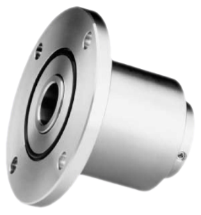
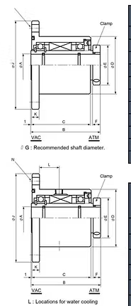
| Shaft Diameter | 010 | 020 | 025 | 030 | 040 | 050 | 075 |
|---|---|---|---|---|---|---|---|
| A | Ø10 | Ø20 | Ø25 | Ø30 | Ø40 | Ø50 | Ø75 |
| B | 78 | 82.5 | 88 | 93 | 96 | 98 | 115 |
| C | 64 | 68.5 | 74 | 79 | 80 | 82 | 96 |
| D | 51 | 63 | 71 | 78 | 90 | 103 | 143 |
| E | 34 | 44 | 49 | 54 | 69 | 79 | 109 |
| F | 10 | 10 | 10 | 10 | 12 | 12 | 15 |
| J | 90 | 105 | 120 | 120 | 145 | 160 | 210 |
| K | 10 | 10 | 10 | 10 | 10 | 12 | 12 |
| L | 20 | 22.5 | 26 | 27 | 27 | 26.5 | 33 |
| M | PD70/4-□10 | PD85/4-□10 | PD100/4-□10 | PD100/4-□10 | PD120/4-□10 | PD135/4-□10 | PD185/4-□10 |
| Model Number | MFL010CN | MFL020CN | MFL025CN | MFL030CN | MFL040CN | MFL050CN | MFL075CN |
|---|---|---|---|---|---|---|---|
| Torque capacity (kg·cm) | — | ||||||
| Vacuum pressure Pa,(Torr) | 10⁻⁶, (10⁻⁸) | ||||||
| Leakage rate [He] (Pa·m³/sec) | <10⁻¹² | ||||||
| (Torr·ℓ/sec) | <10⁻¹¹ | ||||||
| Pressure capacity [Static] (kg/cm²) | 3 | ||||||
| Temperature range (°C) | 0 – 150 | ||||||
| Gas compatibility | Inert Gas | ||||||
| Bearing type | 16003 | 6906 | 6907 | 6908 | 6910 | 6912 | 6918 |
| Bearing material | SUJ2 | ||||||
| Housing material | SUS303 | ||||||
| Shaft material | SUS630 | ||||||
- Conflat flange is available as an option.
- Tapped bore type model number should change to MFL-000-WN.
Hollow Shaft — Cantilevered Seal Type
Hollow Shaft · Cantilevered Seal Type
A hollow-shaft feedthrough for single-side support structures or special mounting conditions. With a reactive-gas-capable seal structure, it is chosen for equipment where standard flange types are difficult to apply.
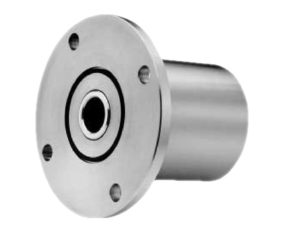
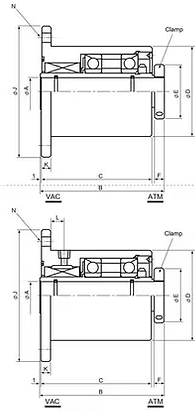
| Shaft Diameter | 020 | 025 | 030 | 040 | 050 |
|---|---|---|---|---|---|
| A | Ø20 | Ø25 | Ø30 | Ø40 | Ø50 |
| B | 123.5 | 126 | 130.5 | 141 | 147.5 |
| C | 109.5 | 112 | 116.5 | 125 | 131.5 |
| D | 78 | 90 | 96 | 106 | 132 |
| E | 44 | 49 | 54 | 67 | 79 |
| F | 10 | 10 | 10 | 12 | 12 |
| J | 120 | 145 | 145 | 160 | 185 |
| K | 10 | 10 | 10 | 12 | 12 |
| L | 14.5 | 13 | 14 | 12 | 12.5 |
| N | PD100/4-□10 | PD120/4-□12 | PD120/4-□12 | PD135/4-□12 | PD160/8-□12 |
| Model Number | MFF020CC | MFF025CC | MFF030CC | MFC040CC | MFF050CC |
|---|---|---|---|---|---|
| Torque capacity (kg·cm) | — | ||||
| Vacuum pressure Pa,(Torr) | 10⁻⁵, (10⁻⁷) | ||||
| Leakage rate [He] (Pa·m³/sec) | <10⁻¹² | ||||
| (Torr·ℓ/sec) | <10⁻¹¹ | ||||
| Pressure capacity [Static] (kg/cm²) | 2.5 | ||||
| Temperature range (°C) | 0 – 150 | ||||
| Gas compatibility | Reactive Gas | ||||
| Bearing type | 7206CDB | 7207CDB | 7208CDB | 7210CDB | 7212CDB |
| Bearing material | SUJ2 | ||||
| Housing material | SUS304 (SUS316 : Option) | ||||
| Shaft material | SUS630 | ||||
- Conflat flange is available as an option.
- Tapped bore type model number should change to MFL-000-MC.
Multi-Axis · Coaxial Feedthroughs
Multi-Axis & Coaxial
A combined-drive product family that transmits multi-axis rotation or rotation + linear motion in a single feedthrough. Applied to semiconductor and display transfer robots.
Two Coaxial Type
Two-Axis Coaxial Type
A dual-coaxial structure that is small and lightweight yet offers high rotational accuracy and low runout. A representative application is in-vacuum wafer transfer robots (SCARA type).
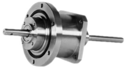
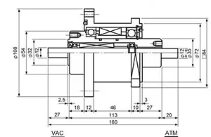
| Model | MFF012NN |
|---|---|
| Vacuum pressure Pa,(Torr) | 10⁻⁶, (10⁻⁸) |
| Leakage rate [He] (Pa·m³/sec) | <10⁻¹² |
| (Torr·ℓ/sec) | <10⁻¹¹ |
| Pressure capacity [Static] (kg/cm²) | 2 |
| Temperature range (°C) | 0 – 150 |
| Gas compatibility | Reactive Gas |
| Bearing type | (out) ATM6007, VAC6908 / (in) 6901 |
| Bearing material | SUJ2 |
| Housing material | SUS304 |
| Shaft material | SUS630 |
Three Axis Type
Three-Axis Type
A three-axis structure providing rotational accuracy and low runout with high rigidity. An optional aluminum housing enables a lighter assembly, and it is applied to LCD large-glass-substrate transfer robots (Frog arm type).
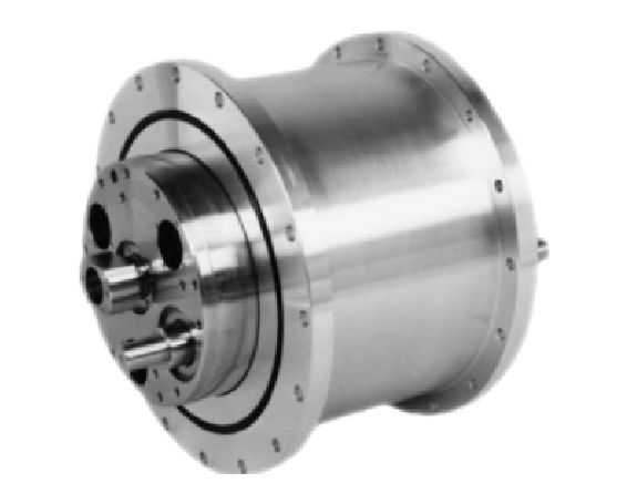
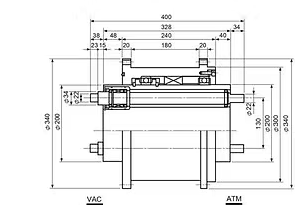
| Model | MFL200NN |
|---|---|
| Vacuum pressure Pa,(Torr) | 10⁻⁶, (10⁻⁸) |
| Leakage rate [He] (Pa·m³/sec) | <10⁻¹² |
| (Torr·ℓ/sec) | <10⁻¹¹ |
| Pressure capacity [Static] (kg/cm²) | 2 |
| Temperature range (°C) | 0 – 150 |
| Gas compatibility | Inert Gas |
| Bearing type | (out) 6840 / (in) 6906 |
| Bearing material | SUJ2 |
| Housing material | A2024 |
| Shaft material | SUS630 |
Three Coaxial and Linear Feedthroughs
Three-Axis Coaxial + Linear Feedthrough
A combined-drive feedthrough coupling a high-rigidity three-axis coaxial spindle with a 50 mm linear stroke. For Cluster Tools, it is applied to 300 mm wafers, LCD large-substrate processing, and in-vacuum transfer robots.
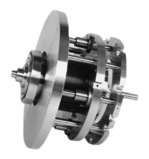
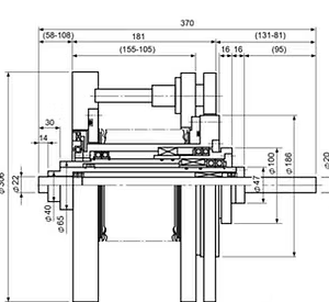
| Model | MFF022NN |
|---|---|
| Vacuum pressure Pa,(Torr) | 10⁻⁸, (10⁻⁸) |
| Leakage rate [He] (Pa·m³/sec) | <10⁻¹² |
| (Torr·ℓ/sec) | <10⁻¹¹ |
| Pressure capacity [Static] (kg/cm²) | 2 |
| Temperature range (°C) | 0 – 150 |
| Gas compatibility | Reactive Gas |
| Bearing type | (L) VAC6814, ATM6816 / (M) VAC6808, ATM6909 / (S) 6804 |
| Bearing material | SUJ2 |
| Housing material | SUS304 |
| Shaft material | SUS630 |
| Bellows stroke | 50 mm |
| Bellows life | OVER 10⁶ |
Special-Purpose Feedthroughs
Special Purpose
Feedthroughs designed to handle special process conditions such as ultra-high vacuum, reactive gases, and gas supply.
Ultra High Vacuum Feedthroughs
Ultra-High Vacuum (UHV) Feedthrough
A product for transmitting rotary motion in high- and ultra-high-vacuum environments. With low-vapor-pressure UHV ferrofluid and a differential-pumping structure, it supports vacuum down to the 10⁻⁷ Pa (10⁻⁹ Torr) class.
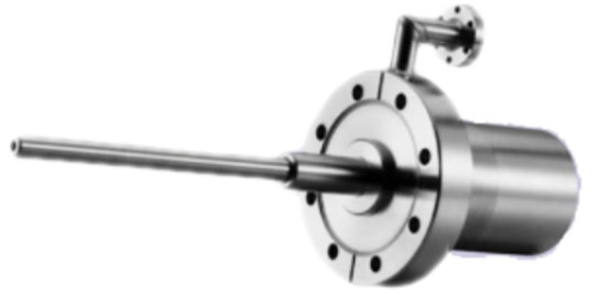
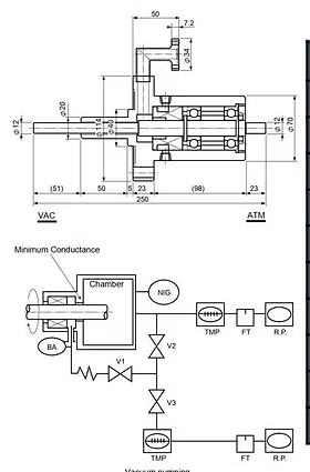
| Model | MSCV-012WC |
|---|---|
| Vacuum pressure Pa,(Torr) | 10⁻⁷, (10⁻⁹) |
| Leakage rate [He] (Pa·m³/sec) | <10⁻¹² |
| (Torr·ℓ/sec) | <10⁻¹¹ |
| Pressure capacity [Static] (kg/cm²) | 2.5 |
| Temperature range (°C) | 0 – 150 |
| Gas compatibility | Inert Gas |
| Bearing type | 7303CDB |
| Bearing material | SUJ2 |
| Housing material | SUS304 |
| Shaft material | SUS630 |
- Ferrofluid for UHV operation, which has low vapor pressure at high temperature, is used.
- The main chamber is protected from bake-out gas by differential pumping.
- Baking condition is the same as for a TMP.
- The differential pumping line and main pumping line can be unified up to a 10⁻⁹ Torr vacuum level.
- The compact equipment can be provided with a simplified seal construction for UHV processing.
Purge Mode Type
Purge Mode Type
A purge-gas structure in the seal unit suppresses process-gas/contaminant ingress into the seal area and deposition buildup. Suitable for deposition processes such as reactive gases, CVD, and furnaces.
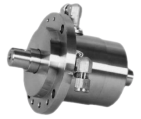
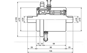
| Model | MSFV-020WC |
|---|---|
| Vacuum pressure Pa,(Torr) | 10⁻⁶, (10⁻⁸) |
| Leakage rate [He] (Pa·m³/sec) | <10⁻¹² |
| (Torr·ℓ/sec) | <10⁻¹¹ |
| Pressure capacity [Static] (kg/cm²) | 2.5 |
| Temperature range (°C) | 0 – 150 |
| Gas compatibility | Reactive Gas |
| Bearing type | 7006CDB |
| Bearing material | SUJ2 |
| Housing material | SUS304 |
| Shaft material | SUS630 |
- Longer life is realized by installing a purge-gas structure in the seal unit.
- This prevents process gas from flowing into the seal area and eliminates deposition near the seal.
- Intended for reactive-gas, CVD and furnace applications that generate depositing material.
Rotary Gas Union
Rotary Gas Union
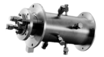
A feedthrough that supplies or exhausts high-purity gas through the rotating shaft. Applied to process equipment that must connect a gas line while maintaining rotary motion.
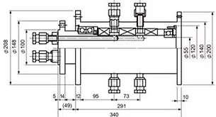
| Model | MSFH-100NH |
|---|---|
| Vacuum pressure Pa,(Torr) | 10⁻⁶, (10⁻⁸) |
| Leakage rate [He] (Pa·m³/sec) | <10⁻¹² |
| (Torr·ℓ/sec) | <10⁻¹¹ |
| Pressure capacity [Static] (kg/cm²) | 3.5 |
| Temperature range (°C) | 0 – 150 |
| Gas compatibility | Inert Gas |
| Bearing type | (left) 7015CDB / (right) 6211 |
| Bearing material | SUJ2 |
| Housing material | SUS304 |
| Shaft material | SUS630 |
- Highly purified gas can be supplied into a chamber through this feedthrough.
- A typical application is a rotary gas union for light-bulb manufacturing equipment.